Some Basic Electronics for Radio
 Do you ever wonder how sound that goes into a radio transmitter comes back out of a radio receiver as sound, when you can't hear any sound along the way? Sometimes it's easiest to pretend that everything that happens inside these devices is magic, and only the wizards and witches inside need to understand the magic. We can say that a transmitter is a "black box" that turns waves of sound into waves of electricity and a receiver is a black box that turns electricity back into sound. But if you ever need to build one of these devices, or fix one that breaks, then it helps to know a little about how the electronic stuff works. The electronics used in radio, known as radio frequency or RF electronics, is a vast subject with entire books devoted to it, and there's no way we can explain it all in one document. Instead, we'll try to explain some of the most fundamental theory and the most common components used in RF electronics, with the hope that it will be enough to get you started.
What is Electricity?
All matter is made up of positively and negatively charged particles, called protons and electrons, respectively. (Well, okay, there are also neutrally charged particles called neutrons, but those are fairly uninteresting for our purposes.) Oppositely charged particles (protons and electrons) are attracted to each other, and similarly charged particles (protons and protons, or electrons and electrons) repel each other. When protons and electrons are distributed evenly in matter, the charges cancel each other and we say that the matter is balanced or neutrally charged. But when extra protons or extra electrons accumulate in matter, the matter becomes positively charged or negatively charged. Static electricity is when positively charged matter and negatively charged matter attract and repel each other. If we connect a positively charged object to a negatively charged object with a conductive pathway (a path through which electrons can travel, such as a wire, salt water, or a metal doorknob), we get what we call electric current when the electrons travel from one object to another to balance the charges. By changing the characteristics of this electric current, we can transmit information such as the sound in a radio broadcast.
Some Terminology
charge
- Charge (symbolized by Q) can be thought of as a collection of electrons (or their absence) in a container, such as a battery or a metal sphere. The basic unit used to measure charge is the coulomb (abreviated as C), which is the amount of charge contained in about six quintillion electrons.
- current
- Current (I) is the rate at which electrons move. Current is measured in amperes (A), or amps for short, where one amp is equal to one coulomb per second. If we imagine that we can represent charge as water particles and a wire as a hose for charge to flow through, then the current in a wire is the rate of flow of the water. Current comes in two forms - direct current (dc), the continuous flow of electrons that we get from a battery, and alternating current (ac), the varying flow that we get from a wall outlet.
- voltage
- Voltage (V), also called potential difference or electro motive force (EMF), is the amount of work required to move a unit of charge from one point to another. The standard unit for voltage is the volt (V). One volt is equal to one joule per coulomb. (A joule is the amount of work required to move an object that weighs about one quarter of a pound across a distance of one meter.) Voltage is usually measured relative to the voltage of the earth. The earth contains so many protons and electrons that it can absorb an immense amount of charge and still be fairly well-balanced, so we say that the earth is at 0V, or ground. If we put a neutrally charged metal plate near the earth and move one coulomb of charge from the earth to the plate, and it takes us one joule of work to do so, then we can say that the plate has a voltage of 1V relative to ground. If we then connect a wire from the plate back to the earth, one joule will be released as one coulomb of charge flows back to the earth, and the voltage of the plate will return to 0V. In our water analogy, voltage is like water pressure, and charges will move from areas of high pressure to areas of low pressure. Ground is like a giant reservoir where we can dump as much charge as we like.
- power
- Power is the rate at which work is done, measured in watts (W), where one watt is equal to one joule per second. We can calculate power by multiplying current by voltage (P=IV). In RF electronics, the power of the transmitter determines the strength of the signal.
A Circuit is a Series of Tubes
We can control electricity by building circuits. A circuit is a path for electricity to flow through. A number of different components control the amount and type of electricity that travel from one point in the circuit to another. A circuit is analogous to a system of plumbing pipes and valves that control the flow of water in a building. A schematic diagram is a diagram that uses symbols to show how the components in a circuit are connected.
Basic Components
- resistors
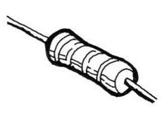
- A resistor is a device used to reduce the current in a circuit. A resistor works by absorbing some of the kinetic energy from the moving electrons and turning it into other forms of energy (such as heat). Some resistors are fixed and always provide the same amount of resistance, while others are variable and can be adjusted to provide more or less resistance. Returning to the water analogy, a fixed resistor is like a smaller diameter section of hose, and a variable resistor is like an adjustable valve on the hose. The unit for resistance is the ohm (Ω), where one ohm is equal to one volt per amp. When a voltage difference is present across a resistor, the current through the resistor will be proportional to the resistance. This can be expressed mathematically as V=IR, a relationship known as Ohm's law. When there is no conductive pathway through a circuit, the circuit is said to be open, and the resistance is infinite (no current flows). When there is a perfectly conducting pathway, the circuit is said to be shorted and the current is infinite. In reality, even the most perfect wire has some resistance, so the current is never infinite, just very large.
- capacitors
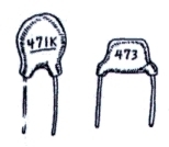
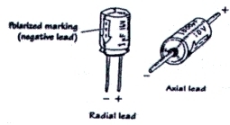
- A capacitor is a device that stores charge. The simplest capacitor consists of two conductors separated by a dielectric (a material with very high resistance). If we attach the two plates of a capacitor to the two terminals of a battery, charge will flow to or from the plates until one plate has the same potential as the positive terminal of the battery and the other plate has the same potential as the negative terminal of the battery. After this initial charging/draining, no current will flow in the circuit, so we say that the capacitor blocks dc current. However, if we attach the plates to the terminals of an ac current source, the current source will constantly charge and discharge onto one plate. The other plate will become discharged and charged in response, due to the attractive and repulsive forces from the first plate. Current will not literally flow from one terminal of the capacitor to the other, but it will seem like it is doing so as the plates charge and discharge. We can imagine a capacitor as a rubber membrane across a pipe -- the membrane does not allow water to pass through, but it does transmit pulses. The capacitance (C) of a capacitor is measured in farads (F), where one farad is equal to one coulomb per volt.
- inductors
- An inductor is a coil of wire whose behavior is the opposite of that of a capacitor. Because an inductor is simply a wire, it passes dc current easily. When an ac current hits an inductor, though, it creates a magnetic field that (because of the inductor's geometry) opposes the current flow, effectively blocking ac current. An inductor is like a paddlewheel in a pipe -- the wheel will resist changes in flow rate, but once it settles at a certain speed it will allow water to flow by easily. An inductor's inductance is measured in Henries (H), and is determined by the length of the inductor, the number of turns, and the material around which the wire is wound.
- diodes
- A diode is a component that allows current to flow in one direction while blocking current flow in the other direction. A diode has two ends, called the anode (positive end) and the cathode (negative end). When the anode is more positive than the cathode, the diode is said to be forward-biased and allows current to flow. When the cathode is more positive than the anode, the diode is reverse-biased and blocks current. A zener diode is a special kind of diode that acts like a normal diode when it is forward-biased, but also allows current to flow when it is reverse-biased if the voltage difference between the anode and the cathode exceeds a characteristic breakdown voltage. In the water analogy, a diode is like a one-way gate with a spring -- water pressure in one direction will stretch the spring and open the gate, while pressure in the other direction will close the gate. A zener diode is like a gate with a weak spring holding it closed in the forward direction and a stronger spring holding it closed in the reverse direction.
- transistors
- A transistor is a device with three pins, where the voltage and/or current on one pin (the base or the gate) controls the amount of current that can flow between the other two pins (the collector and emitter, or the drain and the source). The two main families of transistors are bipolar junction transistors (BJTs), which control current flow based on the current at the control lead, and field-effect transistors (FETs), which control flow based on the voltage at the control lead. We can think of a transistor as a faucet, where the gate or drain is the knob on the faucet controlling the amount of current that can flow through the faucet.
 |
||
| A resistor | Resistor schematic symbols | |
 |
 |
|||
| Ceramic capacitors | Electrolytic capacitors | Capacitor schematic symbols | ||
| An inductor | Inductor schematic symbols |
| A diode | Diode schematic symbols |
 |
||
| A transistor | BJT schematic | FET schematic |
| symbol | symbol | |
| (B=Base, | (G=Gate, | |
| E=Emitter, | D=Drain, | |
| C=Collector) | S=Source) |
